X-ray
Geissler
Crookes
Radio
Box art
Dr. Hugh Hicks
S.Slabyhoudek
M-Jay
Fort Myers, FL.
Monsieur Ara
Fin Stewart
Related links
Submit a link |
|
| Lane-Fox incandescent lamps |
|
| Lane-Fox |
6 files found on 1 page.
Displaying 8 files per page.
|
|
|
|
| [Sort: name hits] [Thumbs/Page: 8 12 16] |
|
 | |  | |  | |  | |  | | c0197
Lane-Fox
1882
Hits: 9961
|
| c0198
Lane-Fox
1882
Hits: 10265
|
| c0200
Lane-Fox
1882
Hits: 10194
|
| c0201
Lane-Fox
1882
Hits: 9669
|
| | |  | |  | | | | | | c0202
Lane-Fox
ca.1882
Hits: 10083
|
| c0208
Lane-Fox
ca.1882
Hits: 1429
|
| | | |
|
|
|
|
|
Early in 2008 I had the oppertunity to obtain a small number of early incandescent lamps produced in England by Lane-Fox. During the course of research I noted a few sources that I thought were interesting and contained valueable information concerning the design and production of lamps made by Lane-Fox. This page ends with excerpts from these works for those interested in the technical details of these lamps.
The Lane-Fox lamps in my collection bear detailed paper labels by L. Clark Muirhead & Co. & the Eastern Electric Light & Power Co. that include the following mostly hand written details:
- Manufacturer name
- Candle power
- Cold resistance
- Hot resistance
- E.M.F. (Electro Motive Force, a cumbersome term used to describe voltage)
- Date (this is probably the date when the electrical measurements were recorded on the label and not the actual production date of the bulb)
- Order number
- Unknown hand written vertical number on the left side of the label
It is speculated that Latimer Clark Muirhead & Company was commissioned by the Eastern Electric Light & Power Company to record and document the precise electrical measurements of these lamps as noted on the hand written labels. Outside of this, the extent of the relationship between L.C.M. & Co. and Lane-Fox is still a bit of a mystery to me.
The Eastern Electric Light & Power Company, formed in 1881, was an offshoot of the Anglo Brush Corporation. During the same time, The Anglo Brush Corporation acquired some Lane-Fox patents subject to the rights of British Electric Light Company. The company exported electrical goods to the far East including Lane-Fox incandescent lamps. The following notice appeared in the January 14th, 1882 issue of The Electrician:
Electric Light For India. -The Malta Standard of 4th January, after referring to the lighting of the Theatre Royal by the Eastern Electric Light Company with Brush lamps, which we have already announced in a recent note, remarks that Mr. J. Fotheringam, the company's engineer, was to sail for India on the 6th January, where the company are about to introduce the Brush and Lane-Fox lamps.
Some more information about the Eastern Electric Light Company can be gleaned from this short bio about engineer G.A. Grindle that appeared in The Electrical Engineer, February 5th, 1892:
Grindle, G. A. Educated privately, and afterwards at Oxford . In 1876 entered the School of Telegraphy and went through a course, and subsequently visited India and America, returning 1880. In the same year entered the service of the Anglo-American Brush Company, passing through the shops, and carried out several installations for them, finally taking charge of the City of London experimental lighting (Brush section) 1881. In 1881 was appointed chief electrical engineer to the Eastern Electric Light and Power Company, Limited, and proceeded to Egypt, where he carried out several installations until compelled to leave at outbreak of Anglo-Egyptian War. Returned to England, and for several months was engaged experimenting for Eastern Electric Light and Power and Indian and Oriental Storage and Electrical Works Companies, Limited, conjointly, chiefly on storage batteries, then proceeded to Bombay to take charge of the Eastern Electric Light Company's operations in India, where he carried out numerous installations. Returned to England in 1884, and was appointed manager to Belfast Electrical Appliances Company, erecting for them various important installations in Ireland. In 1886 entered into private practice in London, and in 1889 was appointed resident engineer for Messrs. Mather and Platt on the City and South London Railway undertaking. He now remains in Messrs. Mather and Plait's service.
It is interesting to compare the tags found on other Eastern Electric labeled lamps and a table is presented below with recorded data from my lamps and those of other collectors who have submitted their lamp data. If you own a Lane-Fox lamp with a similar label, please contact me to add your lamp to the table for comparison and research.
| Lamp specimen |
Candle Power |
Resistance (Cold) |
Resistance (hot) |
E.M.F. |
Date |
Order Number |
Vertically Written Number |
| c0197 (mercury seals) |
20 |
33.5 |
18.4 |
illegible |
5.1.82 |
2889 |
4960 |
| c0198 (crimped copper leads) |
20 |
35 |
19.0 |
44 |
x.x.82 |
2889 |
4092 |
| c0200* (crimped copper leads) |
20 |
32 |
18 |
42 |
2.11.82 |
2889 |
6428 |
| c0201 (mercury seals) |
20 |
34.5 |
20.4 |
45 |
5.9.82 |
2889 |
18/2499 |
| Source #2 (mercury seals) |
20 |
36 |
20 |
44 |
26.9.82 |
2889 |
18/4760 |
| Source #3 (mercury seals) |
20 |
30.5 |
19.19 |
4- (illegible) |
2.8.82 |
2889 |
20/2184 |
| H5994* (mercury seals) |
20 |
36 |
unknown |
unknown |
unknown |
unknown |
18/3013 |
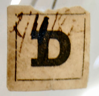
*These lamps contain a secondary small paper label measuring about 3/8" x 3/8" with a single capital letter marked on the label. The TT lamp's secondary label has a capital "D" and a matching hand written date "2/11/82" written over the "D". Click here to view a picture of this label. The H5994 lamp has an identical label with a capital "B" and an illegible hand written date. Fields marked as "unknown" were not visible in the photos provided on the Powerhouse Museum website.
It quickly becomes obvious that all of these lamps have the same order number of "2889" - perhaps a unique number that L.C.M. & Co. used to invoice all Lane-Fox lamps under.
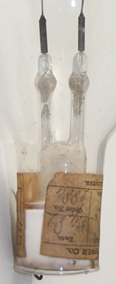
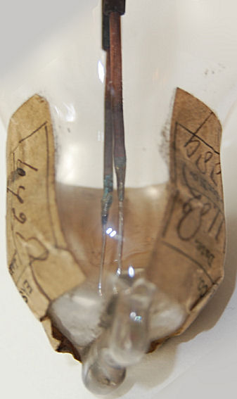
A curious aspect to the lamps in my collection (that I cannot find an answer to) involves the two different construction methods. Oddly, not all of the lamps employ the usual mercurial lead-in wire connections so well known to Lane-Fox lamps. Instead, three of the lamps omit the mercury connection by simply using a piece of copper wire. These lamps also differ in that the glass is pinched off where the electrical leads exit the bulb. Hence, platinum wire is used where the lamps are pinched off, then a copper wire of a larger diameter is used and lastly the familiar drilled carbon cylinders and Indian ink are used to attach the actual filament. The photos below show a comparison made between the two constructions methods, where the left photo illustrates the usual design with the mercury sealed leads, while the right photo shows the simple and crude lead-in wires with the pinched off glass. It seems odd that two completely different designs were utilized within just months of each other.
 |
 |
Mercury sealed leads |
Crimped copper wire leads |
Several Lane-Fox lamps originally existed as part of the William J. Hammer collection of incandescent lamps. These are documented below and this data comes courtesy of Ed Covington's site:
"1881:
- 1881-81------Lane-Fox (English). Early wooden base, vegetable filament, drilled carbon clamps, mercury sealed leads, tip exhaustion.
- 1881-93------Lane-Fox (English). 20-cp, side seal tipless lamp, vegetable filament, drilled carbon clamp, mercury sealed. Made by St. George Lane-Fox.
- 1881-95------Lane-Fox (English). Small tipless side seal, vegetable filament lamp, drilled carbon clamps, mercury sealed around leads.
- 1881-96------Lane-Fox (English). 20-cp, tipless, side seal bulb, vegetable filament, drilled carbon clamps, mercury sealed leads. Made by St. George Lane-Fox.
1882:
- 1882-39------British Electric (English). Improved Lane-Fox lamp, vegetable filament, carbon clamps, tipless, bottom seal.
- 1882-43------British Electric (English). Improved Lane-Fox lamp. Carbonized vegetable filament, carbon clamps, tipless globe.
- 1882-98------Lane-Fox (English). 20-cp, 61-volt, vegetable filament lamp, drilled carbon clamps, mercury sealed around leads, tip sealed. Made by St. George Lane-Fox on April 22, 1882.
1883:
- 1883-45------British Electric (English). Improved Lane-Fox lamp, tipless, bottom seal, vegetable filament, carbon paste clamps."
Pharmaceutical Journal and Transactions
|
Aug. 5th,1882 |
"The International Electric Exhibition (1881 Paris Exhibition)
The next Englishman to tread in Mr. Swan's steps in this field was Mr. St. George Lane-Fox. The following description of this inventor's lamp by the Paris committee is very full and clear, but further detail as to the manner in which the contacts are made will be found of interest and will therefore be given after the description. "The Lane-Fox lamp is ovoid in shape, the neck being in length intermediate between the two lamps last described (Swan and Maxim). The carbon is in the form of a horseshoe, and is circular in cross-section. It is made from the root of an Italian grass, largely used a France for making brooms. After carbonization the filaments are classified according to their resistance. They are then heated in an atmosphere of gas, by which carbon is deposited upon them, as is the filaments of the lamps last described. The filament in the lamp is supported by platinum wires, to which it is attached by sleeves of carbon encircling both. These wires pass through tubes in the top of a hollow glass stem. Just below the extremities of these tubes are two small bulbs containing mercury, forming the contact between the platinum wire sealed into the glass above and the copper conductor which enters from below. These conductors are held in place by plaster, which fills the base of the lamp." The filaments are joined to short cylinders of carbon or graphite by means of holes drilled a little way into them; these holes are filled up with a cement composed of genuine Indian or Chinese ink and finely divided plumbago. At the other end of the cylinders holes are drilled to meet the ends of the filament, but the inventor states that this is not absolutely necessary. In these latter holes short lengths of platinum wire are inserted, cemented as before; each length of platinum wire need not extend 3/4 of an inch in length. The other ends of the platinum wires are fused into tubes of lead glass and the wire ends come into the small glass globes filled with mercury. The mercurial contacts are arranged as stated by the committee.
The Italian grass from which the filaments are manufactured is stated by the inventor to be the Chrysopogon Gryllus. The grass is prepared by boiling in a 5 percent solution of caustic soda or potash; the outer skin is thus loosened and scraped off. The fibre is straightened by stretching it while still damp, and the straightened fibre is bound on a block of carbon, buried in plumbago in a sealed crucible and the crucible and its contents raised to a white heat. The fibres are thus ready for mounting as before described. If the resistance of the carbonized fibres proves to be too high Mr. Lane-Fox ingeniously incandesces them in a "Woulfe's" bottle contrivance; through which a stream of coal gas or hydrocarbon vapour is passing continuously. The filaments are in connection with a measuring apparatus when the resistance is found to be nearly right, the filaments are mounted in their holders and the process repeated until the resistance reaches the exact figure necessary.
The Lane-Fox lamp was found by the Paris Committee to have a mean resistance cold of 55 ohms: at 16 candles this resistance became reduced to 27.4 ohms, and at 32 candles to 26.59 ohms. The current required when yielding 16 candles was 1.593 amperes with an electromotive force of 43.63 volts; at 32 candles the current was 1.815 ampères and the electromotive force 48.22 volts; 10.61 16 candle lamps were yielded per horse-power and 8.65 32 candle lamps, being 173.58 and 276.89 candles per horse-power.
The Lane-Fox lamp is worked by the Anglo- American Brush Electric Light Company. The luxurious richness of the installations of Lane-Fox lamps in the Alhambra Court at the Crystal Palace made the Brush Company's exhibit one of the most popularly attractive sights of the exhibition. The display was certainly an impressive demonstration of the ornamental capabilities of the incandescent electric lamp, such as cannot be imagined by those who had not the fortune to see it." |
|
|
Useful Information on Electric Lighting by Killingworth Hedges
|
1882 |
"The Lane Fox Lamp.
This system resembles both those previously described. The horse-shoe form of Edison is adhered to, but the filament instead of being larger at its extremities remains the same size, and is fixed into two little cylinders of plumbago, which are also connected to the platinum wires, each fixed in a glass tube containing mercury, in which dip the connections leading from the exterior of the lamp.
The filament is composed of stalks of grass or of vegetable fibre vulcanised and impregnated with chloride of zinc. To form the vacuum in the lamp the Sprengel pump is not employed, but an improvement of a barometrical air exhauster, which has been used for the production of the vacuum in the well known Geissler's tubes.
Seven lamps have been worked per horsepower, each having a lighting power equal to 12 candles. The resistance of each lamp measured when cold varies between 75 to 105 ohms, when hot it is about 45 percent less. This system is employed for the illumination of the reading-room at the South Kensington Museum , a Brush machine furnishing the current to a number of 20-candle lamps." |
|
|
The Modern Applications of Electricity by Édouard Hospitalier, Julius Maier
|
1883 |
|
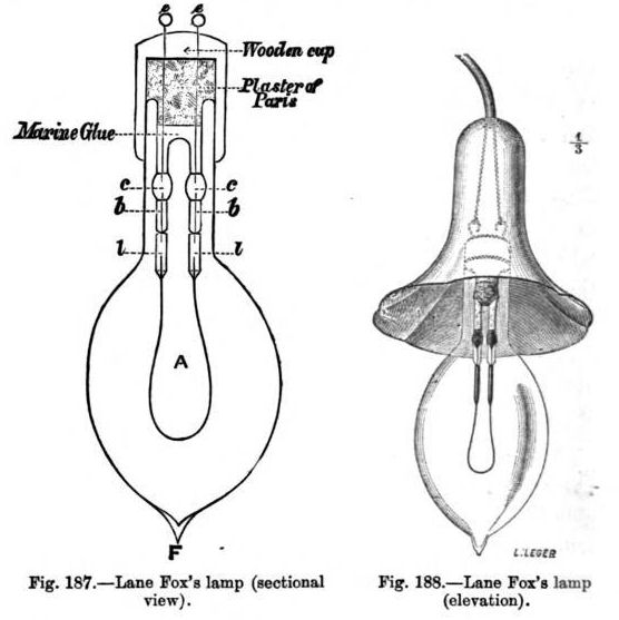
"Lane Fox's Lamp.-Fig. 187 gives a sectional view, and Fig. 188 a perspective view, of the lamp. The light results from the incandescence of a continuous conductor made of a filament of carbon. This conductor is of high electrical resistance, so that a comparatively small amount of electricity driven through it develops sufficient heat to produce incandescence. The filament is enclosed in a glass globe, from which all deleterious atmosphere has been as completely removed as possible.
In the diagram of the lamp, the curved line A represents the luminous conductor, which consists of a carbon filament, prepared by baking a strong cotton thread or string in a hermetically sealed vessel at white heat. Conductors may be made in this manner with a resistance of several thousand ohms for only a few inches length.
In order to reduce this resistance and to produce a harder and more durable carbon, Lane Fox adopted a plan, first suggesting by Sawyer, of New York, of heating the conductor to incandescence whilst immersed in a hydrocarbon liquid or gas; but this process is not by any means essential. Referring again to the diagram, 1 1 are carbon cylinders, into which the ends of the carbon filaments are secured. A small hole is drilled through these cylinders, and into these holes the ends of the carbon thread fit tightly. A very good cement for fixing these carbons may be made out of plumbago and Indian ink. The ends of the platinum wires are beat into eyes e e, into which the hooks of the holder are inserted.
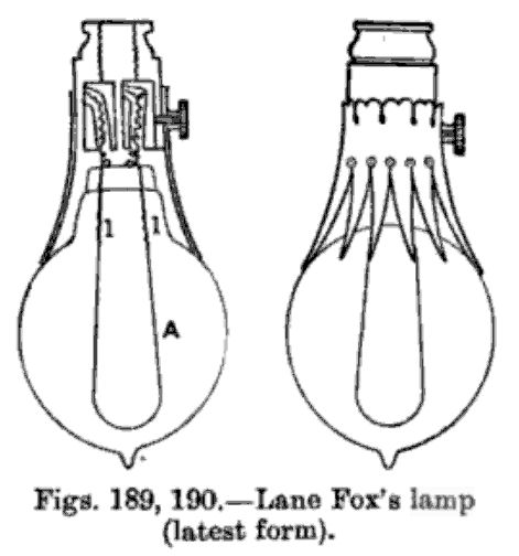
Figs. 189 and 190 show the latest form of the Lane Fox lamp.
The filament employed in these lamps is made from grass fibres, preferably that known as French whisk, or bass broom, and used in making certain kinds of carpet brushes. The fibre is first cleaned by boiling in a strong solution of caustic soda or potash, and the outer skin scraped off. The soda or potash is then boiled out of it, and a number of fibres are stretched round a mould or shape of plumbago, and are then baked in a plumbago crucible at a white heat. After being baked in this manner, the fibres are further carbonized by depositing carbon upon them from a rich hydro-carbon gas, such as benzole. For this purpose they are suspended in large globes filled with benzole or coal-gas, and then heated to incandescence by the current. The white-hot filament decomposes the gas, and carbon is deposited on its surface, especially at the thinner parts, where the temperature is highest. In this way the fibre is covered with a hard skin of carbon, which brings it to the required resistance and renders it more uniform throughout-a point of some importance as affecting the durability of the filaments. Instead of employing the electric current in this way, Mr. Lane Fox carbonizes his filaments by raising the benzole receptacle to a white heat in a furnace.
After being carbonized in this manner, the fibres are classed according to their thickness, and are ready for mounting in the lamps. Slight differences of thickness occasion great differences in resistance, and the thicker specimens are reserved for lamps of thirty to sixty candle-power, whilst the smaller ones are kept for lamps often to twenty candle-power." |
|
|
A Practical Treatise on Electric Lighting by
James Edward Henry Gordon
|
1884 |
|
"The Lane-Fox Lamp
Mr. Lane-Fox's process is probably not very different from that adopted by other manufacturers. As it happens, however, that I have had an opportunity of inspecting it somewhat closely, I will describe it in detail, not saying that it is better or worse than other processes, but as an illustration of what the general nature of all the processes is. The filaments are usually prepared from the fibres of the bass broom.
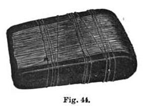
About 100 pieces of fibre, cut to the right length, are bent round a block of carbon, and secured to it by winding string round, as shown in fig. 44. Some fifty of these blocks are prepared, and placed in layers one above another in a crucible, all the interstices between them being filled with powdered charcoal, with which also the crucible is filled up to the top.
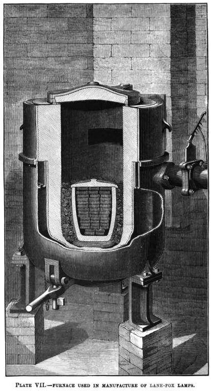
The crucible is then placed in a small furnace (Plate VII.), and the temperature gradually raised up to full whiteness. The crucible, with its contents, is kept at a full white heat for some twenty minutes, after which it is allowed to cool. On being taken out, the fibres are found to be converted into hard carbon of a rough, porous texture and of high and unequal resistances.
Plate VII. shows the details of the arrangements of the furnace used by Mr. Lane-Fox as constructed by Messrs. Fletcher.
We note that there is a perforated diaphragm which causes the draught to circulate evenly round the crucible.
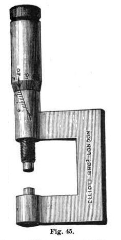
A furnace and crucible of the size shown will carbonize about 5000 filaments at one heating. Fig. 45.
The next process is to gauge the fibres with a wire gauge reading to 1/1000 inch (fig. 45); they are then sorted, so that all of the same diameter are placed together for the making of lamps of the same radiating surface.
If S be the surface, L the length, and D the diameter, we have,-
S=3.1416 D L . . . . . (44)
Example.
A filament is 2 inches long and .018 inch diameter, what is its surface?
We have from (44),-
S=3.1416 x .018 x 2 = .1031 of a square inch.
The next operation is the equalizing of the resistances, and the hardening and smoothing of the carbon. This is accomplished by means of what is called a flashing- bottle.
The carbons are placed, one by one, with their two ends in two spring clips, so that a current can be sent through them. These clips are fixed into a cork, so that they can be placed inside a bottle,- through which a stream of coal-gas is constantly flowing.
On a current being sent through the filament so as to render it incandescent, carbon from the gas commences to deposit on it, and the filament becomes denser and smoother, and its resistance rapidly diminishes. The process is stopped when the resistance has reached exactly the desired amount. As the resistance diminishes, the brightness of the light given by the filament in the flashing-bottle increases.
When the workman, judging by the light, considers that the resistance has reached its proper value, he removes the filament from the bottle and tests its resistance (cold) by a Wheatstone's bridge. After a little practice the workmen are able to obtain the resistance correct to about one ohm, by judging the brightness of the light, in one or two tries, or "flashes," for each filament.
By means of the ohmmeter, it might be possible to obtain the hot resistance accurately without taking the filament out of the bottle.
The thickened ends of the filaments consist of two little cylinders of carbon, which are drilled from end to end. The ends of the filament are inserted into the holes at one end of each cylinder, and the platinum wires which pass through the glass of the lamp are inserted into the other ends. The filament and platinum wires are secured by a cement of which Indian ink is the chief ingredient.
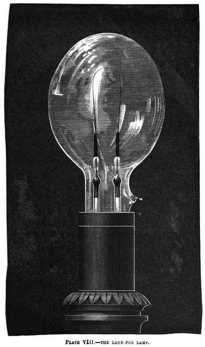
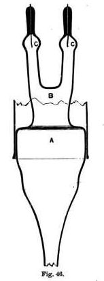
The construction of the glass part of the lamp is seen in Plate VIII. and in figs. 46 and 47.
The globe is prepared with a sufficiently wide neck to admit the carbon loop (which is sufficiently elastic to be considerably bent without breaking).
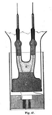
A glass piece (fig. 46) is prepared, having two narrow tubes, into the points of which are melted little pieces of platinum wire, about 3/16 inch long. The carbon is attached to these wires in the manner already described, and the forked piece being inserted in the globe, the neck of the globe is melted on to the wide part of it in a blow-pipe flame. The upper piece is taken off, so that the neck is hollow and funnel-shaped, as shown in fig. 47.
A fine tube is then melted into the side of the neck for exhaustion. A little mercury* is put from outside into each of the tubes of the forked piece, and copper wires put in so as to dip into the mercury at C. The mercury forms an electrical connection between the copper and platinum, and at the same time prevents any leakage of air where the platinum passes through the glass. The hollow neck is filled up with cotton-wool (B), and with plaster of Paris (A), which holds the copper wires and the mercury in their places. The lamp is now ready for exhaustion.
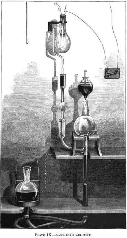
This is accomplished by means of a pump invented by Mr. Lane-Fox, and shown in Plate IX.
*The whole of this part of the process is antiquated, but it is of some historical value as showing the difficulties which had to be overcome in the early days of lamp manufacture.
The Lane-Fox Pump
The pump consists essentially of two large globes connected by a tube, partly of glass partly of india-rubber. The glass part (A) of the tube is vertical, and is some 35 inches long, and one globe is fixed at the top of it. The other globe is moveable, and is connected to the lower end of the fixed glass tube, by a length of india-rubber tube sufficient to allow the moveable globe to be hung by its wire handle to either of two hooks, one of which brings it above the fixed globe, while the other is below the level of the bottom of the fixed glass tube. The top of the moveable globe is open to the air.
Enough mercury is put in the apparatus to fill the tube and one globe.
A side tube branches out from the fixed tube near the top, and turns up and passes vertically a little higher than the top of the fixed globe.
A lamp, or generally two lamps at a time, are attached to the top of this tube.
In the vertical part of the side tube is a valve consisting of a cylindrical enlargement, inside which lies a hollow glass stopper. On mercury rising in the side tube, the stopper floats up and closes the tube sufficiently tight to stop mercury from passing up to the lamps. The mercury surrounding the stopper prevents air passing it.
At the top of the fixed globe is a valve worked by hand, consisting of a glass stopper surrounded by a second smaller globe. To close the valve the stopper is inserted, and a little mercury or sulphuric acid put in the smaller globe surrounding it. The stopper prevents the liquid from passing from the small to the large globe, and the liquid prevents the entrance of air.
When the pump is worked, the moveable globe is hung on the upper hook, so that the mercury rises in the fixed tubes. In the side tube it rises as far as the valve, which it closes; while in the main tube it rises and fills the fixed globe, the stopper being withdrawn to allow the air to escape.
Some strong, pure sulphuric acid is then put into the smaller globe, and the moveable globe lowered sufficiently to allow a little of the acid to enter the large fixed globe, where it lies on the top of the mercury. The stopper is then inserted, and the moveable globe completely lowered and hung on the lower hook.
The mercury sinks, leaving a complete vacuum in the upper globe until the column is lower than the opening of the side tube, when the valve in the latter opens and the air in the lamps rushes into the large globe.
The moveable globe is then again raised, and the rising mercury closes the valve leading to the lamp; and the air, being directed into the fixed globe, escapes through the stopper valve, which is opened for the purpose. Meanwhile the sulphuric acid removes every trace of moisture. We see that the ratio of the quantity of air in the lamp after each stroke is, to that before the stroke, as the volume of the lamp is to the sum of the volumes of the lamp, tube, and fixed globe.
After a few minutes' work the lamp is completely exhausted, as is shown by the sharp click with which the mercury strikes the top of the fixed globe on the moveable globe being raised.
The filaments are then brought to a state of vivid incandescence, and the pumping recommenced, and continued for a few minutes more, until the greater portion of the gas contained in them has been expelled and removed. They are, however, kept on the pump and incandescent for some twelve hours, a stroke being taken only occasionally to remove the last trace of gas. The lamps are then sealed off in the ordinary way, and are ready for use."
|
|
|
Dynamo-Electricity by George B. Prescott
|
1884 |
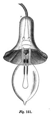 |
"The form of the Lane-Fox lamp (figure 151) is very similar to the Edison; both make a single loop of the carbon, which is bent into a horse-shoe form. The filament of the Lane-Fox lamp is made from grass fibres of the kind known as French whisk or bass broom, used in making carpet brushes. The fibres are boiled in a strong solution of potash or soda, and the skin scraped off and then the soda or potash is boiled out of them, and they are stretched around a mould of plumbago, and baked at a white heat. The fibres are then further carbonized by depositing carbon upon them from a rich hydrocarbon gas. This is done by suspending them in large globes filled with bengole, and then heated to incandescence by an electric current. The gas is decomposed by the white hot filament, and carbon is deposited on its surface, by which means the fibre is covered with a hard carbon skin, which produces the requisite resistance and renders the filament more uniform, thus insuring greater durability. The carbons are of various thickness, some being used in lamps of 10 and 20 and others of 30 and 60 candle power.
Mr. Lane-Fox's method of distributing the current is similar to Edison's, except that he uses the earth instead of a return wire. The lamps are placed in multiple arc and a constant electro-motive force of about 100 volts is maintained in the circuit. An automatic regulator is employed to insure this result, which is placed in the circuit between the main conductor and the earth. The regulator (figure 152) consists of an electromagnet, E, through which a shunted portion of the current passes, and attracts the armature of lever L, pivoted at H. This lever plays between the two adjustable contact pins I and v, resting midway when the current is of the proper intensity, but striking the upper pin I, if the current becomes too strong, and the lower pin v, if it becomes too weak. By this means a local circuit is closed, and more or less resistance is inserted in the circuit of the field-magnets of the generator, so as to bring the lighting current to its normal value, and the lever of the regulator to its mid position. This resistance is inserted automatically. E is a vibrating electro-magnet, analogous in its action to the buzzer of an electric bell, which is caused by the local current to rotate a vertical axis N, carrying at its upper end a small toothed pinion, which can gear with either of the two like wheels R and R', enclosing it between their toothed edges. If it gear with the wheel R, the horizontal spindle D, carrying these two wheels, will be rotated in one direction, and if it gear with R' the same spindle will be rotated in the other direction, and as the spindle D carries at its lower end a vertical shaft connected with the sliding contact arm F, F, which moves over the contact pieces c, c, of a series of resistances contained in the box, it throws in or takes out resistance from the field magnet The direction in which the horizontal spindle shall turn is determined by the two electro-magnets E and E'. According as the lever L touches I or v, one or other of these electro-magnets E or E' attracts the armature A, placed between their opposed poles, which moves the spindle D longitudinally, and brings the pinion- headed axis into gearing with one or other of the two wheels R and R' on the horizontal spindle.
Secondary batteries are used to store any surplus current and return it to the circuits when there is any falling off in those below the normal current They are so arranged that the battery in discharging will automatically adapt the potential of its discharge to the needs of the mains as determined by the regulator.
Mr. Lane-Fox has invented three kinds of meters for measuring the current used in his lamps. The Lane-Fox system is now worked by the Anglo-American Brush Electric Light Corporation, and was exhibited with fine effect at the Crystal Palace Exhibition, where the Alhambra Courts were lighted by Lane-Fox lamps fed from a Sellon-Volckmar secondary battery charged by a Brush machine, and the light was conveniently graduated by switching on a greater or less number of cells of the battery." |
|
|
Electricity in the Service of Man by
Alfred Urbanitzky
|
1886 |
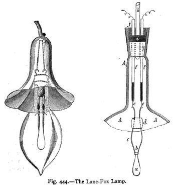 |
"Glow Lamps by Lane-Fox (Fig. 444).-Two wires e e, which are connected with the mercury tubes f, are attached to the metal springs c, which are the carbon holders. These springs are regulated by the slide d, consisting of insulating material. The tubes f and h pass through an india-rubber cork g; i is a layer of mercury, and over it is a layer of cement j. The glass vessel is exhausted by means of the tube h.
Lane-Fox prepares the carbon filaments for his lamps in the following manner: Hemp threads are wound round a piece of coke having a knife-edge at one side; and the whole is placed in an oven. During carbonisation the threads contract and are cut by the knife-edge. In this manner carbons of the same length are obtained. Benzole, or similar vapour, is used for carbonising the filaments, whilst the carbons are made white-hot by means of the electric current The ends of the filaments are connected with a short piece of wire (short-circuited), and again a current passes through them. The lamp is constructed in different sizes, and for an intensity of 87 candles, 66 volts by 0-673 ampere are required." |
|
|
The Incandescent Lamp and Its Manufacture by
Gilbert Scott Ram
|
1894 |
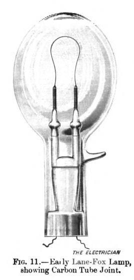 |
"All these [filament attachment] methods, which were used in the early days of lamp-making, have, however, been abandoned as unsatisfactory or too costly. The filaments were apt to work loose, owing to expansion and contraction with temperature. In the earlier forms of the Lane-Fox lamp a hollow carbon tube was used, into which the platinum wire was inserted at one end and the filament at the other, with some kind of carbon paste to make the joint firm." |
|
|
Related links:
|
|
|
|


