THE MÜLLER INCANDESCENT LAMP.
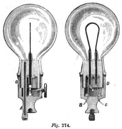
Mr. Müller's incandescent lamp is shown partly in section in two views in fig. 274. In this lamp the inventor secures the following important results: First, replacing the carbon filament without breaking or rendering useless any part of the lamp; second, preventing the entrance of air through the joints between the plug and the conductors passing through it to the carbon filament.
The glass globe or bulb is provided with a flaring strengthened neck, fitting very tightly on a bevelled glass stopper or plug, which, is secured air-tight by means of packing material in a hollow base, D, adapted to be screwed on or otherwise attached to a bracket or chandelier arm. The glass plug and the neck of the globe are ground together so as to fit air-tight against each other. A packing is placed around the plug and the edge of the neck as shown. Two carbon conductors of suitable thickness are passed through longitudinal openings in the glass plug, projecting from the top and bottom of the plug, and secured in the plug by a suitable cement forming air-proof joints.
Copper rings are cast or blown into the top and bottom of the plug around the apertures through which the carbon conductors pass, and these rings project slightly from the ends of the plug. Copper is then precipitated by means of electricity around the projecting ends of the carbons and the rings. By this means the projecting ends of the carbons will be strengthened and prevented from being broken off and the joint will be made air-tight.
The upper ends of the carbons are provided with slots into which the ends of a carbon filament are passed and secured by means of a peculiar cement. A glass seal tube projects from the bottom of the plug through the base of the lamp, in which it is secured air-tight by means of cement. The end of this tube extends through the plug, and is contracted at its upper end. This tube is stopped at both ends, and the intervening space is filled with mercury.
Two insulated spring-contact strips project upward from the bottom of the recess in the lamp base, and rest against the lower projecting ends of the carbons. These strips are connected with conducting wires, B C, leading to the electric generator. A key journaled in the lamp base has at its inner end a cross piece, which is of sufficient length to separate the strips and remove them from the ends of the carbons when it is in a horizontal position. When this cross piece is in a vertical position, the strips are released and rest against the ends of the carbons.
Should the carbon filament be destroyed or broken, the globe is removed, a new filament is inserted, the globe is replaced, and the air is exhausted. |