X-ray
Geissler
Crookes
Radio
Box art
Dr. Hugh Hicks
S.Slabyhoudek
M-Jay
Fort Myers, FL.
Monsieur Ara
Fin Stewart
Related links
Submit a link |
|
| Diehl Incandescent lamps |
|
The Telegraphic Journal and Electrical Review |
May 13th, 1882 |
|
"Diehl's Incandescent Electric Lamp. - We illustrate a new incandescent electric lamp, patented by Mr. P. Diehl, of Elizabeth , New Jersey , U.S.A. The idea of the inventor, which is ingenious as far as the globe is concerned, can best be conveyed by the words of his specification, which are as follows:-
One of the main objections of electric vacuum lamps, based on the principle of incandescence, consisted in the leakage of the lamps, as owing to the difference in the expansion and contraction of the glass globe and of the conducting wires, air will gradually get in and destroy the vacuum established therein, so as to render the lamp useless.
The object of this invention is to furnish an improved electric lamp, based on the principle of incandescence, in which the light giving part of the lamp is inclosed within an evacuated and hermetically sealed glass globe, without any wires passing through the body of the globe to the interior of the same. And the invention consists of an electric lamp, composed of a hermetically sealed glass globe, and a light-giving part, supported at the interior of the globe, and placed in circuit with a secondary coil, which is arranged within an extension made integral with the globe, and placed in inductive relation to a primary coil exterior of the lamp.
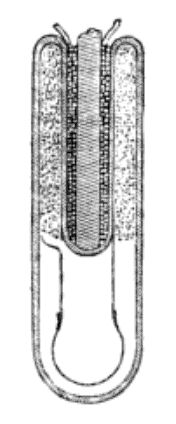
The accompanying drawing represents a vertical transverse section of my improved electric lamp The carbon filament or other light giving part is held between the terminal wires of the secondary coil, so as to be in the same circuit therewith, said light-giving part being made of any desired shape and material, and connected in any approved manner to the conducting wires. The primary coil is connected by the conducting wires with the poles of a magneto or dynamo-electric machine, arranged for alternating currents, or with a battery or other source of electricity. In the latter case an automatic current-breaker has to be placed in the circuit.
The change of polarity, or the closing and breaking of the current in the primary coil, will induce currents in the secondary coil at the inside of the lamp, the rapid succession of which will heat up the light giving part to incandescence, and establish thereby a steady and reliable light, that is not liable to the interruptions caused by the gradual destruction of the vacuum, and that will consequently be of much longer duration, owing to the entire absence of leakage."
|
|
|
International Electrical Exhibition--1884, of the Franklin Institute |
1884 |
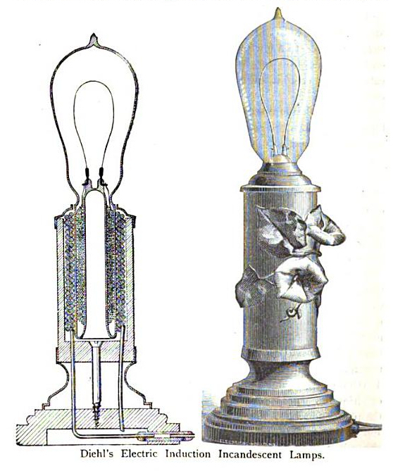
DIEHL'S ELECTRIC-INDUCTION INCANDESCENT LAMP.
In the exhibit of the Singer Sewing Machine Company, the committee found several ingenious forms of incandescent lamps in which no terminal wires penetrate the glass, the whole action depending upon induction through the glass.
These lamps were devised by Mr. Philip Diehl, of Elizabethport NJ., and require an intermittent current to develop the inductive action; the current from the dynamo does not enter the lamp, but passes into a coil of wire which surrounds a glass tube, forming the base of the bulb. Inside the tube is a second coil, whose terminals are connected with the carbon filament, and when the intermittent current is passed through the outer coil, a secondary current is induced in the inner coil, which heats up the carbon to the point of incandescence.
The inventor stated that the best form of lamp which he had been able to produce on the induction principle, has an interior or secondary coil of only four layers of No. 30 B. & S. gauge, uncovered copper wire. The first layer is wound directly on the inwardly reaching tube of the glass globe, the other layers are insulated from each other by thin sheets of mica, the wire being wound so that there is no point of contact. Naked copper wire is used in preference to insulated wire coil to facilitate the subsequent evacuation of the bulb, as any form of insulating material tends to retard the perfect exhaustion. In order to increase the inductive action, bundles of iron wire are inserted in the centre of the tube, around which the secondary coil is wound.
The weight of copper wire used for the interior coil is one third of an ounce.
The exterior coil consists of but two layers of naked copper wire, No. 16 B. & S. gauge. These layers are insulated from each other with asbestos paper, the weight of wire being three and one half ounces.
The exhibitor claimed that the largest lamp shown would give a light of about forty candles, and stated that he had run five of those lamps with an expenditure of one horse power, and that he was confident that still better results could be obtained when the true proportions of the coils are found by further experiments.
Another style of incandescent lamp was shown, having interior and exterior condensers, intended to be used with currents of very high electro motive force, as in the Geissler, or Crookes tubes, except that there are no terminal wires liable to become heated, and so destroy the seal. The condensers form a sort of accumulator, so that when the current of electricity is momentarily interrupted, the steadiness of the light will not be affected.
After some difficulty, owing to the absence of the inventor and the want of a suitable dynamo for this purpose, the committee succeeded in operating two of the lamps, by introducing a circuit breaker, but it was not possible to make any tests, either of the candle power of the light or the power consumed, but the committee is able to state that the carbon filaments glowed with a steady and fairly brilliant light; and while no opinion is expressed as to the practicability of this form of lamp, it was thought that it possessed sufficient novelty and interest to warrant a brief notice in this report. |
|
|
|
Electricity in the Service of Man by Alfred Urbanitzky, Richard Wormell |
1886 |
|
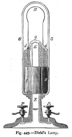
Diehl's Lamp.
The chief difficulty in the construction of glow lamps is to fuse the wires so as to leave no places in the glass vessel which will allow air to enter. Diehl in constructing his lamp avoids this difficulty by having no wires at all fused into the glass. The glass bulb of the lamp (Fig. 449) consists of two tubes gg and G G, closed at their upper ends, their other or free ends being fused together. The inner tube is surrounded by insulated wire d d, the ends of which are joined to the carbon B. Inside the inner tube there is an iron rod E having a few turns of thick wire round it. The ends of this wire lead to the clamps P P. When alternating currents are used for this lamp, as they flow through the turns of the thick wire, they cause in the thin wires d d induced currents, which bring the carbon to a glow. When continuous currents are to be used, a self-acting commutator has to be inserted. This lamp is much more expensive than other glow lamps under equal conditions, as the current of the generator has to be converted into induced currents, and this conversion always involves loss of energy. |
|
|
Related links:
|
|
|
|


